Edge Blending with Projectors at an Angle
-
@alexwilliams said:
pixel stretch and luminosity fall off
Hi,
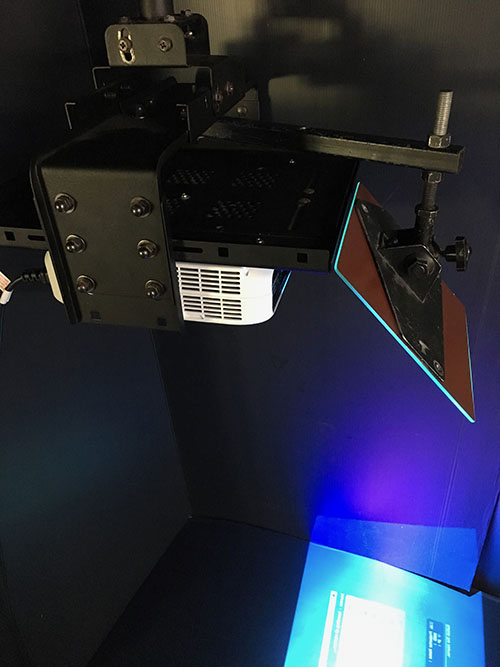
It is hard to know what impact the conditions will have, because there a so many variables. Many projectors are now designed to rotate through the projection axis 360°. If your projector is not designed to operate at the angle you intend it may be worthwhile checking the operating manual. It will likely tell you that if you go beyond a certain angle the lamp life will be reduced. The real issue is the cooling system of the projector and how air moves past the bulb to keep it at an acceptable operating temperature. On the other hand, if your projectors are 360° axis they may already have built in calibration to deal with the issues you are anticipating. I use a couple of 8K Epson large venue projectors that are 360° and the operating angle needs to be set in the onboard menu settings before the projector will even function beyond a few minutes - so they do internal calibration based on its operating angle and refuse to continue operating until the angle is set. To be kind to a non-360° projector, another option may be to project through a rig with a mirror. This photograph shows a rig I put together recently for a non-360° projector - it has a glass mirror suspended on a universal joint in front of the projector lens - so the image could be reflected at many different angles and quickly adjusted for the venue and rigging location.

The other variables are to do with what content you are presenting and how far away from the screen the audience are who will be aware of individual pixels. Some projectionists set the focus just off so that pixels blend. There may be a compromise focus setting that is visually acceptable.
Regards
bonemap
-
@fred
I guess for me it seems the chopper is more accurate in that you can enter numerically how to divide the image.
This is difficult in the mapper currently. -
@fred Can you show more detail about how you would split the output?
-
@alexwilliams I don't have a machine close, but I take the output from a movie player actor that, for example is playing a a 3840*1080 movie. I send the same signal to two projectors. Here just double click on a projector O open the mapper and line up the portion you are mapping.
I like to line up the edge of the real world projectors to something visible in the real world. This makes it easier to line up the pieces, especially over the blended area.
There is no bypass control on the blend, bit I write down or screen shot the parameters and map one physical video at a time without blend and then go back to the blend to make everything smooth.
-
@fred Can you clarify a couple things for me when you create the slices in the mapper, on my end it stretches the image for the output, which I have to eyeball back into position so it isn't stretched on the output of the mapper. Is there any way to not have it stretch? I'd like to be precise. I think this is why @DusX and @bonemap were going for panners and choppers?
The other issue is I'm guessing where to slice the image so that it corresponds to the other image - instead of knowing exactly where it is. That's not a huge problem, as I can blend it in stage setup, but again, I'd prefer to be precise.
Also, just wondering - do you use the alignment grid or do you use another test pattern - meaning not one in the projector, but an image of one, to line up the blend? Just thinking if there's something patterned in a regular way, it might be best for blending.
Many thanks, Alex
-
@alexwilliams I think as you dont know exactly how many pixels you are overlapping (unless you make some very fine measurements) you will always have to adjust manually. Yes the first output of the mapper is stretched, just line up the corners you know (so the far left and far right of a 2 projector blend) and try get the geometry right. I would do this without the blend enabled, just get the overlap correct. Then you need to use a better calibration image, the isadora one will not work; make one the same dimensions as your full image. Something like a UV map is useful but you see the point (this image is quite important for the job, spend the time making a good one):

If you have some circles you will also be able to see if you are keeping your aspect ratio (this will change from the angle of projection - corrected by the stage setup) as well as the mapper in to out ratio (corrected by the mapper). The squares on this image might be ok too as you can measure them easily on the projected image to make sure they are still square. Again make sure you have a test image the same size and aspect ratio as your projected image.
Once the outer edges are lined up it will be a process of adjusting the input and output quads to get the blend correct and get the aspect ratio correct (possible going back to the stage setup warping as well. Once you are happy with the alignment move on to the blend. I start with all white for the blend and switch back to a range of colours. It will pretty much never be perfect, but with ok projectors (a high contrast ratio) you can get it pretty good, and if there is ambient light then it will hide imperfections you cannot correct for like black over the blend).
There is an updated system coming in the next release, but unless you can calculate everything to the pixel, which is very hard and almost impossible with an angle, you will alway have this back and forth to get this right.
One thing I am not sure about is if the mapper uses sub pixels, (I think it does but maybe someone knows for sure). This can make it a bit better to work with than the chopper as when you have an angle your pixels get progressively bigger as you move away from the axis, having subpixel control over input and output sources can help this.
I have done some very annoying work blending projectors on big angles and it is not so hard, but make sure you give yourself ample time and it will be OK, don't rush and be prepared to go back to earlier steps if you need to correct them. Only annoying thing is you cannot save multiple versions of the stage setup as it is saved with the machine not with the patch, so comparing solutions is hard.
Fred
-
@fred Thanks very much this is great. Do you ever use @michel 's suggestion of Vioso's website - http://www.vioso.com/softegde_... to create an image for mapping with? @mark can you answer the question about the mappers and subpixels?
Thanks,
Alex
-
@alexwilliams The visio image is OK, personally I prefer more and smaller detail, the three big circles are not enough for me, especially if you are mapping on a building. The other issue is that I find it important to have the calibration exactly the same resolution and shape of the final video, and I like it to come from the same software and export pathway. To some degree the logic is not good on the visio site, it asks for overlap, which is very very hard to know exactly. Rather than look at it that way, I imagine I will have my source that needs to be mapped across a blend and this has a pixel size. I will then create a canvas out of multiple projectors that can fit and display this image.
Still in a pinch it is a nice resource.
-
@fred - Thanks again. We're mapped to our overlap now, in an unusual blending situation - we've got two 1280x800 projectors set on their sides horizontally, and projecting at an approx 25 degree angle coming from two sides. Our problem now is to know how to find the pixel count of our resulting perspective-corrected mapped image - we're projecting a normal perspective image on a flat screen from angles because we have to - it's rear projection and we have no space to do otherwise, and because we don't want hotspots through the rear projection - we're projecting on a cyc that isn't designed for rear projection...
I'm wondering how to find out what the pixel count is, so we can create our projected images to be able to project across both projectors.
By the way, when we mapped this we found that the vioso map did indeed not work. The image vioso saves would only be useful if the projectors were straight on, not if they're on an angle.
-
@alexwilliams there is not perfect way to get the final complete resolution. I would make up an image with colour bars in 10 pixel vertical stripes. Make some with opposing colours, put these up on your projectors without any mapping or correction, count how many bars are overlapped and you will get close to knowing your total pixel count.
-
@fred Great solution.
We're now having the issue that our mapped area doesn't have the functionality of being able to place the content we're projecting to both screens - that's blended - to move freely from side to side. Of course the image is mapped, so we'd need to put something in between the projector and the movie player. We've tried the zoomer, but it strangely makes our stage smaller and gives a background (white) to our image, so it's of no use, frankly. Do you have a suggestion for how to place content dynamically on both screens? We can use the spinner to rotate images, we just need to be able to travel along the x and y axes.
Best, Alex
-
@alexwilliams said:
something in between the projector and the movie player
Hi Alex,
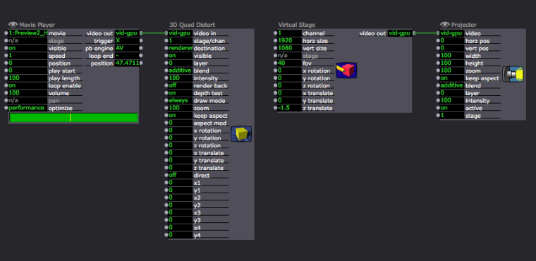
The combination of '3D Quad Distort' and 'Virtual Stage' has the potential to provide the flexibility that you are describing.

Best Wishes
bonemap
-
@bonemap Thanks very much - my problem is though that I have two stages blended, so I want to move the image before it gets to the two mapped and blended projectors. At the moment I go straight from a movie or picture player to my mapped projectors. So I need to be able to move the image across the two stages. Since the Quad Distort and the Virtual Stage only control one channel/stage at a time, I can only control one of the two projectors - which throws my map and blend it out of whack... Any thoughts?
-
@bonemap actually that worked! thanks so much!
-