[ANSWERED] Inverse kinematics using 3D player and Calc Angle 3D actors
-
@bonemap
Russell, yes, I can look at it now. Thank you for sharing it. Your approach is similar to what I am doing, except I am not using Calc Angle 3D actor and am using the equation: angle=arctan(distance opposite angle/distance adjacent angle).Perhaps I am wrong, but I suspect an obstacle for getting a correct inverse kinematic calculation is that the octant containing the target coordinate must be considered when calculating a joint's angle. I suspect the calculation method will be different in different octants(individual xyz coordinate are positive or negative).
https://en.wikipedia.org/wiki/Octant_(solid_geometry)If Mark is reading this, can you confirm if the Calc Angle 3D actor considers the octant in its calculations of angles? I created a user actor that determines the octant of a vector pair(XYZ1joint > XYZ2 target), see attached. It outputs the octant using the numbers 0 to 7. For example, octant 6: X is +, Y is +, Z is -
decimal to binary equivalent:
0=000: - - -
1=001: - - +
2=010: - + -
3=011: - + +
4=100: + - -
5=101: + - +
6=110: + + -
7=111: + + +I have not successfully determined the correct calculation for each octant, but I notice that an angle calculation method will work in certain octants but not others. Feel free to check it out using the attached actor
regards,
Don
-
@dritter said:
I am not using Calc Angle 3D actor and am using the equation: angle=arctan(distance opposite angle/distance adjacent angle).
I have definitely considered using the geometry math directly to solve this challenge, as you have attempted. I would not have the skill to tackle this efficiently and so my strategy has been to approach a more capable programmer. But, like everyone I have to weight up the priorities in my productions and schedules.
It is tantalising to get so close, and to see you get so close, to a solution. At some point I would have to stop tinkering with the Art of it and turn to some hired help and it is this investment that I have to weight up.
We can nudge @mark, but we would need the interest from more Isadora users for the 3D space to become priority. Having said that, the release of the OpenNi tracker and other spatial tracking tools suggests a simple workable solution, such as the ‘Calc 3D Angle’ module would be well placed to help users realise their visions for digital real-time puppets and avatars.
@mark has hinted at the solution of using a game engine to fulfil the demand for 3D interactivity, such as Unity3D or similar, then linking control commands through Isadora. So I ask you Don, just out of curiosity, why have you persisted to try and tackle this in Isadora, rather than use a dedicated 3D real-time interactive program?Personally, I have been seduced by attempting to get everything within the same package. The linking of nodes in a single patch interface appears to offer less limitations in terms of efficient data interactions. And another thing, it appears achievable with the resource nodes that Isadora offers, therefore as my enquiry into the program develops I am also exploring its limits as aN artist and designer. When we approach those limits, as we are now, it is also pushing for continued learning and discovery.
Best Wishes
Russell
-
Hello Russell, thank you for the insightful questions. I have spent many hours over the past two years on my current Isadora project, and control of 3D characters is part of an overall system that produces four independent audio channels and a 6K video projection controlled by the body gestures of 3 persons. I am moderately familiar with 3D animation software(3DS Max) and I know what Unity is capable of doing, but I am not familiar with Unity as a user and am reluctant to learn another software. Having the capability to control 3D characters within Isadora is convenient from a practical and system perspective. I have tried getting inverse kinematics to work within Isadora, but suspect I am being limited by my lack of knowledge of 3D mathematics and matrices. I have read various academic papers on inverse kinematics over the past few weeks, but I cannot even understand their nomenclature. I have learned, however, that I was initially naive in understanding the complexities of inverse kinematic calculations, but am not ready to give up yet... well maybe, almost...
all the best,
Don -
Over the last few weeks I have been in contact with Anomotion, a company that an creates a plugin for translating 3D data into a moving 3D character with IK. This plugin is usable only with the Unreal Engine for creating VR and computer games.
-
Dear All (and specifically @bonemap and @dritter)
I'm going to take a stab at trying to explain how Isadora processes rotations. As much as I might be confident I am a decent programer, 3D math and visualizing spatial relationships in 3D is not my strong suit. Some of what I am about to say below might be totally wrong because of my inexperience -- so please correct me if I'm wrong about anything I'm about to say!
Please start by downloading the example file attached.
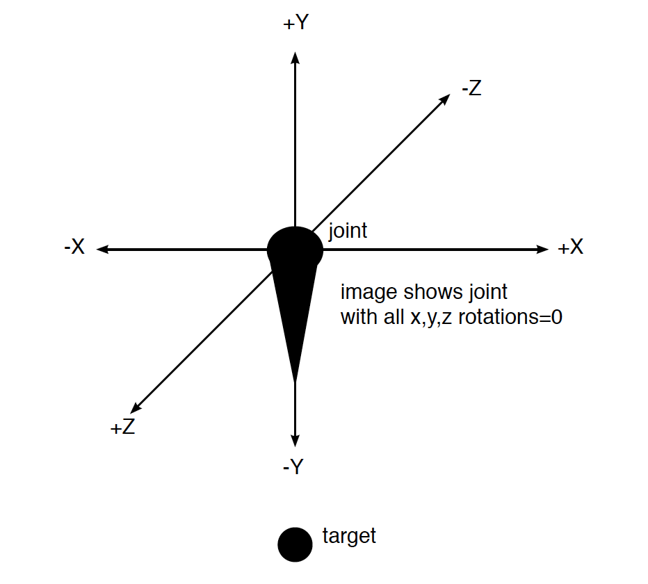
In the first scene you'll see a 3D model that shows the direction of the x, y and z axes. The direction of each arrow shows the positive direction along that particular axis. Before any rotations are performed, you can see that positive x is to the right, positive y is up, and positive z is towards the viewer.
In this and the next next two scenes, pressing letters 'x', 'y' or 'z' will cause a 0° to 360° rotation around the matching axis. At the bottom you can see the current degrees of rotation for each axis.
In the first scene "Visualizing Rotations Z Fwd" start by pressing letter 'z'. You will see that as the rotation value goes from 0° to 360°, the model rotates around the z-axis in a counter-clockwise direction. Try the 'x' and 'y' keys too just to see how it looks or press multiple keys at the same time to see these rotations happen simultaneously.
Then try the same procedure in the next two scenes, labeled "Visualizing Rotations Y Fwd" and "Visualizing Rotations X Fwd", except that you'll press the 'y' key in the second scene and the 'x' key in the third. Again you'll see that when the positive direction of a given axis is pointing toward you, a positive rotation value shows up as a counter-clockwise rotation in the rendered image.
These rotations are all expressed in what is known as Euler Angles (https://en.wikipedia.org/wiki/Euler_angles). As you can see above, Euler angles are sufficient for most use cases in Isadora. But, when you start trying to create a puppet from a tracked skeleton, Euler angles suffer from several limitations that make them difficult to use.
MORE INFORMATION THAN YOU EVER WANTED TO KNOW ABOUT EULER ANGLES
You don't have to read this section, but if you appreciate a learning opportunity, here goes.
One confusing aspect of Euler angles is that, to perform the rotations correctly, you must know the order of the rotations – information which is not specified by the three angles themselves. In Isadora, we always perform the rotations in XYZ order. But it is conceivable to use any rotation order: ZYX or YXZ are just as valid as XYZ and other software or hardware systems might use a different order.
Also problematic is that the angles are going to "roll over" at some point. For example, if an object you are measuring continuously rotates in one direction, going from 0 to 360 and continuing past that point, when you reach 360 it actually changes back to 0 and start over from there. This jump is a major issue if you ever want to use a Smoother actor on those measured angles.
Finally, there is the dreaded "gimbal lock" (https://en.wikipedia.org/wiki/Gimbal_lock) which even the Apollo astronauts had to avoid if they were going to get to the moon and back safely. Suffice to say, if you rotate through a certain combination of angles, you will lose the ability to calculate angles from that point forward. Gimbal lock probably won't come up if you're generating the angles from two points, but it does come up if you ever try to add two sets of Euler angles together. Anyway, since it's the biggest failings of Euler angles when it comes to 3D graphics I thought I should at least mention it.
The bottom line is that Euler angles are a rotten way to attempt to define the orientation of a rigid body in space.
ENTER QUATERNIONS
The Quaternion (https://en.wikipedia.org/wiki/Quaternion) addresses all of the limitations of Euler angles. A Quaternion is composed of four values: three to express a point in space relative to the origin (a three dimensional vector notated as 'x', 'y', and 'z') and a rotation of that vector around it's axis (notated as 'w'.)
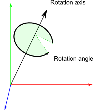
Given two three-dimensional vectors v1 and v2 (composed of [x1, y1, z1] and [x2, y2, v2]) you can create a Quaternion [x, y, z, w] that will transform v1 to v2. Unlike Euler angles, Quaternions never suffer from gimbal lock or rollover, and they do not need to know the order in which the rotations are applied.
The Quaternion is actually what we want to use if our goal is to measure two points in 3D space and then to rotate a 3D model to mimic the orientation of those points. Problem is, we don't have any actors that handle Quaternions in Isadora... well, not until now anyway. ;-)
Luckily, there's a very nice Javascript library called THREE that will do the "heavy lifting" for us. (The compressed source code is included in the download.) Using that library, I've created a Javascript actor called "JS Quaternion Calc Angle" that accepts two 3D points, converts them to a Quaternion, then converts that Quaternion to a set of XYZ Euler angles that can be used by Isadora. Through this two-stage conversion, we end up with stable Euler angles that will give us the results we're looking for.
To help us visualize this, I've created a 3D model called "limb.3ds" that we'll use to represent some part of a body. For purposes of explanation, let's consider the elbow joint and the hand, where the limb.3ds model represents the line segment between them, more commonly known as the forearm.
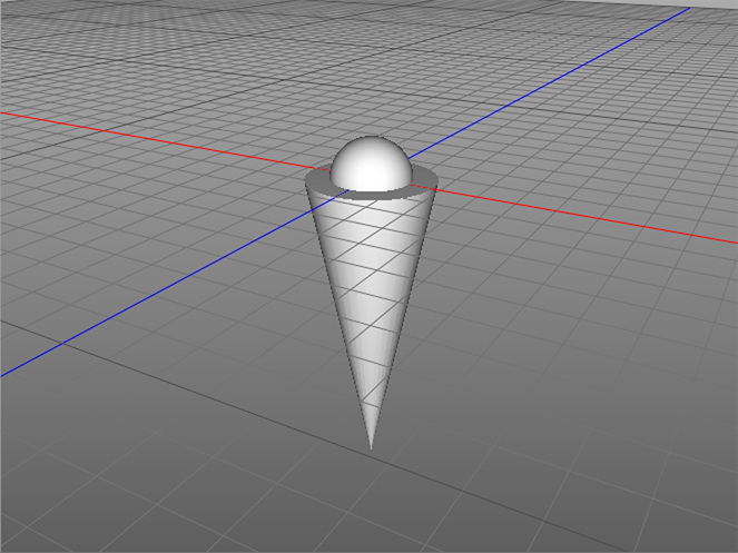
The sphere inset into the wide part of the cone represents the elbow joint and the point of the cone indicates the hand. Note that the "elbow joint" (the center of the sphere) is located at the origin of the model's 3D world, i.e., XYZ coordinate 0,0,0. The "hand" (the point of the cone) ends at the XYZ coordinate (0,-1,0).
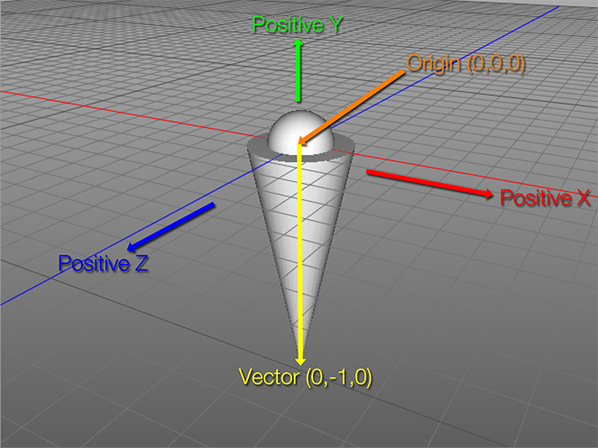
It is important to mention here I've set up the natural orientation of the limb.3ds model so that the vector between the sphere and the point of the cone is straight down (from XYZ coordinates 0,0,0 to 0,-1,0). This orientation that is required by the "JS Quaternion Calc Angle" actor as I've designed it. So, if you make your own 3D models to work with this patch, you construct them in a similar manner.
[NOTE: if you want to have a different orientation for your model, you can modify the Javascript actor's source where it says v1.x = 0; v1.y = -1; v1.z = 0; For example, if you wanted the default position such that the hand (in our example) was pointing forward towards positive-z, you could use v1.x = 0; v1.y = 0; v1.z = 1; instead.]
The model must have its point of rotation at the origin (0,0,0) because Isadora always rotates a 3D model around its origin. In the "real world" your hand is a point that rotates around your elbow. So, if we can feed the correct rotations to the 3D Player, it will rotate the point of the cone around the sphere at the 3D model's origin in a similar manner. Because of this, the order in which you feed x1/y1/z1 and x2/y2/z2 into the JS Quaternion Calc Angle actor is critical. The center of rotation (the elbow for our example) must sent into the x1/y1/z1 inputs and the moving point (the hand) must be x2/y2/z2 inputs -- otherwise the model will move in the wrong direction.
In Isadora, any translation that is applied using the 'x/y/z translate' inputs is performed after any rotations specified by the 'x/y/z rotation' inputs has been applied. So, to get the model into the right place in 3D space, we can simply feed the coordinate of the center of rotation (again, the elbow for our example) directly into the 'x/y/z translate' inputs. To make this easy, the "JS Quaternion Calc Angle" actor. sends its 'x1/y1/z1' inputs directly to its 'translate x/y/z' outputs
With this setup, it now becomes a simple matter to use the "JS Quaternion Calc Angle" actor to accept the two points from your skeleton (with x1/y1/z1 being the center of rotation, and x2/y2/z2 being the point moving around that center) and to then feed the resulting rotations and translations into the 3D Player actor.
EXAMPLE USAGE OF THE JS QUATERNION CALC ANGLE
I've built the Scene called "Quaternion Puppet" using the Rokoko Studio Live Watcher, a plugin currently in beta testing that provides 'skeleton' data from the Rokoko Smartsuit Pro motion capture suit. I leave it as an exercise for the user to get their own motion capture data into this example patch if they wish to try it.
Note that the assumption of the "JS Quaternion Calc Angle" actor is that positive x is to the right, positive y is up, and positive z is towards the viewer. If your device has a different set of orientations, you may have to multiply them by -1 to invert them or otherwise manipulate the values for this patch to work.
The User Actors called "Puppet Two Segments" are is set up to render two segments that are connected by a common joint. For example, a shoulder, elbow and hand.
Double click one of the User Actors called "Puppet Two Segments" and you'll see the following:
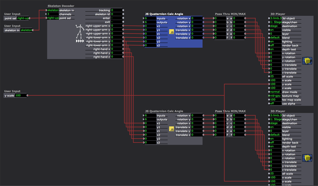
The 'skeleton' input feeds data from the Rokoko actor into the Skeleton Decoder actor, which splits out 3D point data from the 'skeleton' data type.
The 'point sel' input allows me to choose what outputs the Skeleton Decoder will provide to the two "JS Quaternion Calc Angle" actors. In this screenshot, I've used "left-upper-arm,left-lower-arm,left-hand" to split out those points. To use this with other devices, you'd specify a different list to select different points.
Nows comes the two "JS Quaternion Calc Angle" actors. The first receives the x/y/z points for the upper arm (shoulder) and the lower arm (the elbow.) The second one receives the lower arm (elbow) and hand. These actors output the correct rotations and translations needed by the 3D Players down the line.
The "Pass Thru MIN/MAX" was to ensure that the output of the Javascript actor did not adopt the scaling of the 3D Player's 'rotation' and 'translate' inputs. Since the outputs of this actor have their scale min/scale max values set to MIN and MAX, ensuring these values are not scaled by the 3D Player actor.
By using this User Actor four times, I was able to model the arms and legs of a real-time puppet in Isadora. The patch is working well for me, as you can see in the movie below.
https://troikatronix.com/files...
I hope that you all can take this patch and see if it helps you achieve your goals of creating decent real-time puppets in Isadora.=
Best Wishes,
Mark -
-
I don't know if that image represents revelation or a brain exploding. I guess I hope it's both. ;-)
Best WIshes,
Mark -
This is great Mark! thank you very much. I am not yet using Isadora v3, would you happen to have the you puppet file as a v2.6.1?
thank you
Don
-
@dritter said:
This is great Mark! thank you very much. I am not yet using Isadora v3, would you happen to have the you puppet file as a v2.6.1?
Dear Don,
No I don't. But here's the code for the JS Quaternion Calc Angles actor. Perhaps you can build it up from that.
include("three.min.js"); function radToDeg(f) { return f * 180.0 / Math.PI; } function main() { // IZ_INPUT 1 "x1" // IZ_INPUT 2 "y1" // IZ_INPUT 3 "z1" // IZ_INPUT 4 "x2" // IZ_INPUT 5 "y2" // IZ_INPUT 6 "z2" // IZ_OUTPUT 1 "rotation x" // IZ_OUTPUT 2 "rotation y" // IZ_OUTPUT 3 "rotation z" // IZ_OUTPUT 4 "translate x" // IZ_OUTPUT 5 "translate y" // IZ_OUTPUT 6 "translate z" // create v1 from the x1/y1/z1 arguments // this should be one point on a rigid body such as a hand var v1 = new THREE.Vector3(arguments[0], arguments[1], arguments[2]); // create v2 from the x2/y2/z2 arguments // this should be the second on the rigid body such as an elbow var v2 = new THREE.Vector3(arguments[3], arguments[4], arguments[5]);v2.x = v2.x - v1.x; v2.y = v2.y - v1.y; v2.z = v2.z - v1.z; v1.x = 0; v1.y = -1; v1.z = 0; // vectors must be normalized for use with Quaternion v1.normalize(); v2.normalize(); // create a quaternion based on the two vectors var q = new THREE.Quaternion(); q.setFromUnitVectors(v1, v2); var e = new THREE.Euler(); e.setFromQuaternion(q, 'ZYX'); e.x = radToDeg(e.x); e.y = radToDeg(e.y); e.z = radToDeg(e.z); return [e.x, e.y, e.z, arguments[0], arguments[1], arguments[2]];}
-
Great, thank you for spending time on this Mark. I just opened the patch in the demo version of Isadora 3, and it looks like I can rebuild this in 2.6.1. The .js code from your message above is displayed as black text on a grey background, but it becomes white text on a black background starting with the line "v2.x = v2.x -v1"; Is this important?
When I opened quaterion-puppet.izz in Isdora 3, I get the message that 001-one.3ds is missing, and I also get the messageThe following actors/plugins could not be loaded:
Skeleton Decoder (ID = '5F736B6C')
Unknown (ID = '5F736B6C')
Rokoko Studio Live Watcher (ID = '5F737370')
Should I be concerned about the first two items?many thanks,
Don
Don -
Wow! I really don’t know what to say - except to express gratitude for your care and effort!
It is a beautiful thing. The new tool is impressive, but I am astounded and humbled that you have taken so much care in presenting the theory and exemplar in your post. It should really become a knowledge base article, as the articulation back to some of the fundamental understandings of using 3D nodes in Isadora are so eloquently explained.
Best wishes
Russell
-
@dritter said:
The following actors/plugins could not be loaded: Skeleton Decoder (ID = '5F736B6C') Unknown (ID = '5F736B6C') Rokoko Studio Live Watcher (ID = '5F737370')Should I be concerned about the first two items?
No need for concern, those are non-public beta plugins that Mark used in his example, (which is why you don't have them).
-
@dritter said:
Should I be concerned
Hi Don,Considering the level of engagement you are working with using Isadora, it may be worthwhile considering making a request to join the beta testing group. As a beta tester you may be able to access additional resources associated with Isadora3 including the nodes in the download.
@woland, is it feasible to suggest inviting Don into the beta program?
Best wishes
Russell
-
@bonemap said:
is it feasible to suggest inviting Don into the beta program?
Can do!
@dritter
Please submit a new ticket using to link in my signature requesting to join the beta testing group and we can take it from there.
(There's no cost associated with joining and we'll provide you with a temporary Isadora 3 license to test with for a few months.) -
@bonemap said:
Wow! I really don’t know what to say - except to express gratitude for your care and effort!
It was a fun problem to solve. But, you're welcome. ;-)
-
OK, I have submitted a ticket to join the beta group. thank you.
-
Mark, this is very cool.
Three JS also includes physics and collision detection. It would be fun to take this further in this way. -
Happy New Year Mark and many thanks for the IK patch. I was able to reconstruct it for Isadora 2.6.1 and it is working fine with a Kinect and NI-mate. So far I have built IK for the lower arms(elbow-hand) and lower foot(knee-foot), but I have some questions about the following JS code within 'Macro JS Quaternion Calc angle':
// create v1 from the x1/y1/z1 arguments
// this should be one point on a rigid body such as a hand
var v1 = new THREE.Vector3(arguments[0], arguments[1], arguments[2]);
// print('v1 = ' + v1.x + ' ' + v1.y + ' ' + v1.z + '\n');
// create v2 from the x2/y2/z2 arguments
// this should be the second on the rigid body such as an elbow
var v2 = new THREE.Vector3(arguments[3], arguments[4], arguments[5]);QUESTION 1: Is it correct that v1 is the end-effector(or target), and v2 is the rotating joint? I am asking because the IK works for the arm link when v1 is the hand's xyz coordinates and v2 is the elbow's coordinates, but for the foot link, the IK works when v1 is the knee's xyz coordinates and v2 is the foot's xyz coordinates.
QUESTION 2: when the arm link is moved to vertical with the hand straight up, the link rotates 360 degrees around its Y axis(around the spine of the link). Is this normal, or perhaps I have made an error?
QUESTION 3: see below for the orientation of my link. When this link is used for the left or right arm, the IK works correctly when +180 is added to the x rotation provided by the JS Quaternion Calc actor, but this modification is not needed when the link is used for the lower leg. Does this seem normal, or perhaps I have made an error?
many, many thanks Mark,
Don